Jeep Patriot Trailing Arm Bushing Replacement
It's been going on for over 3 years hearing the squeaking and at 110K miles, like anything else in the rear suspension, it was time to fix it. The noise was from the lower rear of the body like old timbers in an old wooding bridge, creaking and groaning. Every uneven rut or a speed bump at low speed, the creaking would reverberate.
The Jeep Patriot has trailing arms, part of the rear suspension and is part of how a vehicle flexes during bumps and turns. The cause of all that racket was the bushings, the item that isolates the shock and vibrations from the road to the body. It was now one of the last things on my list of major replacements for the year, barring any sudden discoveries.
I did embarking on this repair with some research before starting. It is a good idea to know what to expect and to plan out the tools I'll need. However, from only one video and a few user group mentions on the subject, it was shaping to be a project I'll be mostly doing in the dark as for as details.
The video I found was helpful to a point, however, inconsistencies made it more a general reference or outline than an instructional. For example, it was not mentioned about the needed 15mm socket to remove the bolts that hold up the trailing arm, the brake line brackets are also an issue and there was no mention of the stabilizing rods being part of the challenge of loosening the arms. The video gives mentions of sockets, ball-joint tubes kits, pry bar, reciprocating saw, block of wood and jacks, but I would find that this list was overly simplistic. The actual task and the problems encountered will required many times the tools to solve the stumbled upon problems.
Why am I doing it this way?
It might be pointed out that I should just change the entire trailing arm. I'm sure most mechanic would argue it as the right way to deal with this. However, I didn't want to detach the upper and lower control arms, the ABS sensor, the calipers, the hub assembly and axle, the backing plate, the e-brake assembly, the camber links and also requiring a rear alignment job when I'm done. Seemed quicker just to work on the trailing arm bushings by themselves.
The task summary was as follows:
On the driver's side, watch out for the fuel connection, fuel tank, e-brake and soft hydraulic hose as well as the bracket with connection. On the passenger's side, was everything, but not fuel connection. A each items should be managed or dealt with first before allowing the trailing arm to move down. It is very helpful to have a second jack was needed to pivot the arm down to allow for clearance to work without the fuel tank getting the way. Cut a notch in the old bushings, knock them out with a hammer and use the ball-joint press to install the new bushings.
My actual start went this way.
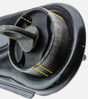
The sided I started on was the left side and first the e-brake cable on its bracket was to be undone from near the trailing arm bolts, after cleaning off the rust, I used a 13mm socket to remove it. After removing the 13mm bolt, it was simple to unhook it from the bracket and moved is aside. The fuel connection might have been disconnected and moved, but I didn't want to fuss with fuel and chose to guard the path of the trailing arm with a pry bar later. However, the brake line must be freed from its bracket or the drop of the trailing arm will strain the line. The brake line connection was held by a flange and secured with a 8mm bolt that is held from behind by a captive nut and I didn't see that at first due to the rust and almost ripped the entire bracket off with the impact gun. I thankfully stopped in time...I hope. Fiddling with the pivoting and gain access to the bushing by placing a bottle jack in the available corner of the hub assembly. Then I marked the positions of the flange's plane in relation to the trailing arm as well the depth of the seated old bushing. These measurements are the guide for the installation of the new bushing.
There is not a good way to describe this part:
Finding the proper angles and pivots points are the next thing. The bushing was held in place with two 15mm bolts. If you unbolt before lifting, the movement of the tailing arm may be managed. However, the trick of the arm will want to move inwards thanks to the little camber link and bring the arms towards the fuel tank. If I thought of disconnecting the links from the trailing arm, then the next procedure might have been less a hassle. I didn't attempt to remove them and maybe I should have. The decision to proceed without removing the camber connections and save me from needing an alignment job later but meant a dance of the little bottle jack on the hub assembly bracket to finesse the flex of the arm to cause the bushing end to pivot down. At a certain amount of lifting as you near the position equal to the normal height when the vehicle is on the ground, the bracket is able to pivot further downward. When the bushing could drop low enough and I could reach with a saw, I stopped pumping the little jack and wedged a block of wood between the arm and the body being careful not to damage the brake line.
The recommended removal of the old bushing was to cut it and this is due to the gas tank's proximity making the ball-joint press not able to fit in the removal position. However, one cut is not enough and depending on how much rust the need to compress the protruding end or outboard side of the bushing, means that multiple cuts are needed to clear the seated diameter of the bushing. It is a good idea to use a wire wheel to remove any rust on it prior to removal of the bushing. If you cut away the rubber core of the bushing, this would make it easier to see and allow careful cutting of the bushing cup. The idea was not to damage the trailing arm itself. In my first attempt I got very close to bottom of the cup and used a hand saw for a few more strokes. It would be thin enough I could simply break the metal. I could observe that the cut compressed closed when I started to hammer on the rim of the bushing cup. So the more cuts the greater the reduction in the diameter. Each time the feathered line of the blade's path starts to disappears from view, I would stop and check the depth with a fine point tool and hand saw the rest of the way. Leaving a thin metal kerf with the few careful strokes, gives a margin of error. When I had four cuts, I started to hammer on them to drive the cup wall inward towards the center at first and then the rim of the bushing to drive it inboard. Two dozen good whacks later, the bushing shot out of the trailing arm.
It is never easy
By the end of the single side, being the left, I amassed a very large pile additional needed tools to tackle the issues I had run into. So far, I mentioned the hand saw. A handy item that takes the saw blades as the reciprocating saw. Painter's tape to mark with a marker the location of the flange angle. Drift punch for flattening the cuts as they bulge. Channel lock wrench to help rock the cup. Wire wheel and drill driver for cleaning up the mounting surface. Pry bars for the few leveraging points needed to keep the trailing arm in position. Clamps to holt the wood blocks in place while hammering the bushing. The one or two wrench sizes grew to my entire tool chest of sockets and box end wrenches. Extra light was needed and the addition of a zip-tie to reduce the slop of the push tube on the holder.

The video also demonstrated the installation of the new bushing with a standard ball-joint press, however, that was not sufficient and I luckily had the large version of the press. In the video, the lack of a pushing tube was a bad example of how to install the bushing. The video shows the guy forcing the bushing without the pusher tube and just utilizing the open tail of the press right up against the bushing. During my attempt, I watched the bushing center distort out of the assembly, it was clear that I required the pusher tube or risk damaging the bushing. However, that was another problem to solve. Due to the poor fit of the tube to the holder, I caused the bushing to go in very slanted and at the risk of having to cut it out. I stopped and was able to back it out with some hit with a hammer.
The Problems with most Ball Joint Press Kits and the Bushing
 |
| This is based on my OTC ball-joint kit |
Although I decided on using the pusher tube arrangement, I discovered how crude the fit between the holder and tube was and it hindering the alignment.
The Left Side:
In my first attempt on the left side trailing arm, I managed to get the parts near poised enough to work and push straight. However, that required a lot of tape to hold them together in groups. I used painter's tape and put the pusher tube holder and then all of that to the end of the bushing.
The Right Side:
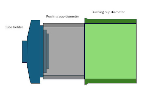
On this side, things were not staying aligned. The holder kept slipping and the pusher tube didn't stay perched on the bushing to drive it correctly towards the receiving tube. This meant I could not turn the press bolt tight enough to lock things straight. It was a challenge to one hand holding the press and tubes with one hand while trying to spin it tight. A couple of tries with the pusher tube tilted and could not stay on the holder even with tape. The tube to the bushing fit was poor (illustration shows the lack of contact space and the tenuous positions).
The Problem:
The rim of the bushing is about 3.125 inches in diameter (O.D.) and a slight more than a quarter inch thick rim, however, the tube was a maximum of 2.755 inches and could only perch on the tip of the inside rim. The holder had stepped shoulders and the closest one didn't properly line up with the tube I selected for the pushing either, as illustrated above. All these misalignments made for a good many failed attempts installing. Only 3/16 of an inch shoulder and the tube had only a slight 1/16 of an inch to perch on the holder's shoulder with plenty of room to fall off. I tried to first solved this by fashioning a spacer from a piece of zip-tie fitted to the inside of the tube and taped down to hold it in position and that did worked a bit.

Although the left side was just stable enough to install and only a few tries to then slide into place, the trial and error attempts on the left side would scar the edges of the tube and holder. The right side could not stay align at all, slipping out due to the rounded edges, each time everything went crooked or wonky would add more rounded edges and scars. After having the dozed attempts on the right side and failing, I returned to an idea I came up with prior to doing all this. When I first tested the tubes fit against the bushings to find the needed tubes from the kit, I quickly discovered the poor fit issue. I had imagined an intermediate plate to correct the poor fit between the two surfaces of the bushing and tube. A simple horseshoe plate to allow the to surfaces to stay aligned during the pressing. So I stopped trying to make the tube seat on the edge of the bushing and went into action to come back after a few minutes with a very nasty piece of metal saw work, ugly filing job as well some viscous licks with the angle grinder. I made something that worked like the above image, however, was very ugly.

Another difficulty was the receiving tube, it was prepared prior to the attempt when I realized it isn't allowing the new bushing to fit inside it. A tube has an inside diameter of 2.756 inch with a scallop opened side. The end of the bushing that should push through the trailing arm and then the receiving tube is about 2.762 inches in diameter. The receiving tube was too narrow for the bushing to fit inside. To solved this, I had my drum sanding attachment and 80 grit sanding tubes mounted on my drill press. Setting the platform to limit my sanding to only 2/5th depth of the opening of the scalloped side. I ground out enough to give the bushing a slightly snug, but easy to slide in and out fit.
With the modified receiving tube, I later pushed it on to the old bushing to mark the depth needed with I mount the new bushing. The correct depth as the original was important to avoid needed an alignment of the rear tracking when all is done. The old and new bushings were the same cup heights and that meant I could easily duplicate the seating of the new bushing later.
When all the loosening and dropping of the trailing arm was accomplished. The clearing of these obstructions allowed me to position the large press and the modified pusher tube with holder and the modified receiving tube with holder around the bushing. A small shot of WD-40 to help things along and started cranking on the press. Finally and slowly I made steady progress. The bushing made its way to the tape mark on the scalloped opening of the receiving tube. The left side done and it took only 4 hours of fussing and making mistakes and fishing more tools. The right side took 3 hours of fussing and making the shim that I should have had for the left side.
The instructions should be as follows:
- Jack Jeep up and secondary jack point and not at pinch weld. You will need the room to work.
- I use a AGM Jack Rod to add safety.
- Have a jack stand, just in case, under the sub-frame.
- Have handy another hydraulic jack for adjusting the trailing arm position to work.
- Tire off.
- Free the e-brake bracket via the 15mm bolt.
- Fee the brake line off of its bracket via the 8mm bolt and not the other side.
- Free the two 16mm bolts holding the trailing arm.
- Guide the trailing arm down to avoid the fuel connector if you are on the left side. If you remove the connection with the trailing arm control arm, this would make things easier, however, the alignment cam should be preserved.
- Make marks to help align the degree of the level of the bushing flanges to the trailing arm as the alignment is not match horizontal to the arm, but tilted.
- When the trailing arm is cleared and in a safe position to work, start cutting the old bushing.
- Taking brief cuts to not cut past the bushing housing and into the trailing arm. The cuts remove the locking tension of the bushing housing to the trailing arm. It should be three or more cuts to make it loose enough to knock out with a hammer.
- Need is the larger version of the "ball joint" press. The 2.75" I.D. receiving tube and the 2.75 O.D. pushing tube. Note: the bushing is about 2.762" O.D. at the point of the seating. My only examples of this tube was at 2.74" and 2.758". I took the 2.74" and used a sanding drum in a drill press to grind away enough clearance to allow the bushing to easily slide into the tube at the full seated depth
- Wire brush slightly the first third of the new bushing to allow for snug seating of it to the trailing arm and align to marks for the angle it should be mounted. Tap in with hammer.
- Tape together the needed tubes and shimming the tubes to fit the holders as centered as possible.
- The press, tubes and bushing on the trailing arm. A small squirt of oil will help too.
- Start cranking on the press until the depth mark is reached.
- The return of the two 15mm bolts are best replaced by remounting the tire and lowering it back to normal to make the alignment and adjusting the bolts easier.
- The remaining bolts for the brake line and e-brake can be down while on the ground. However, I lifted back up and removed the tire to better see the installation.
That is it and I hope it worked.


